Top Welding Lead Connectors for Global Buyers?

Choosing the right Welding Lead Connectors can determine more than connection quality. It can affect safety, uptime, maintenance, and operator confidence. Global buyers often compare copper construction, insulation strength, cable compatibility, and connection stability. These details matter on crowded fabrication floors, where heat, dust, vibration, and repeated bending are normal. A connector may look durable in a product photo. Real performance depends on materials, assembly quality, and working conditions. That distinction deserves attention.

This guide examines leading connector options through practical purchasing criteria. It considers conductivity, current capacity, locking design, temperature resistance, and service life. It also reviews supplier documentation, testing evidence, and consistency between samples and production batches. Experienced welders know that a loose connection can create heat within minutes. A poorly matched fitting may also interrupt an otherwise reliable welding system. Small details matter. Yet no connector suits every application. Market requirements, equipment brands, cable sizes, and local conformity expectations can differ. Buyers should verify specifications with manufacturers before placing large orders. Some product claims still need closer inspection. That is an important limitation. By combining field experience, technical comparison, and supplier verification, this overview helps international purchasers make clearer decisions and reduce avoidable sourcing risks.
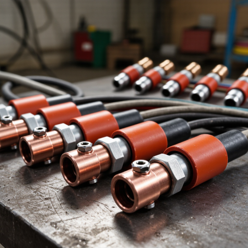
Top Welding Lead Connectors for Global Buyers?

What Are Welding Lead Connectors and Why Do They Matter?

Welding lead connectors are the joining points between a welding machine, work lead, and electrode holder or torch. They carry high current through a flexible cable during welding. A connector is more than a metal plug. It must maintain firm contact, resist heat, and prevent accidental separation.

In field inspections, loose connectors often leave clues: warm housings, darkened metal, or intermittent arcs. These signs can increase resistance and waste power. A properly fitted connector keeps the circuit stable, even when cables move across a workshop floor. The connection should match cable size, current capacity, insulation quality, and the machine’s connection system. Clean contact surfaces matter too. Dust and oxidation may seem harmless, but they can affect performance under load. Shorter cable paths may reduce voltage loss, although real job conditions rarely stay tidy.

For global buyers, reliable documentation is as important as appearance. Ask for rated current, operating duty, material details, temperature limits, and inspection records. Check whether the connector suits the intended welding process and local electrical requirements. A connector that works well in a dry shop may perform poorly outdoors. Weather, oils, repeated bending, and rough handling change the risk. I would not judge quality by a polished finish alone. That can be misleading. Trial fitting, heat checks, and sample testing often reveal issues before bulk purchasing.

How Welding Lead Connectors Work in Different Welding Systems

Top Welding Lead Connectors for Global Buyers

Welding lead connectors transfer current between the power source, electrode holder, and work clamp. In stick welding, the connector must handle high current and frequent cable movement. A secure twist-lock connection reduces resistance at the joint. That matters when welding thick steel at higher amperage.

MIG and flux-cored systems often use separate gun, work, and power connections. Their lead connectors must match cable size, polarity, and duty cycle. TIG systems require greater attention to heat and flexibility. The torch lead may carry welding current, shielding gas, and control signals through different paths. A connector that fits physically may still be electrically unsuitable. Check the rated amperage, insulation condition, and contact surface before installation.

Real job sites are rarely clean. Dust, grinding particles, moisture, and repeated bending can weaken a connection. A practical inspection should look for darkened metal, loose sleeves, cracked insulation, and unusual heat after welding. Small details matter. In generator-powered systems, stable contact becomes even more important because voltage can fluctuate. In automated systems, connector alignment and cable strain relief affect repeatability. Selection is not always neat; a larger connector is not automatically safer. The cable, socket, locking method, and welding process must work together. Even experienced technicians can overlook connector wear during a busy shift.

Top Welding Lead Connectors for Global Buyers: How They Work in Different Welding Systems

The chart compares representative industrial welding-current levels with commonly selected connector capacity classes. MMA and TIG systems generally use medium-size connectors, while MIG/MAG and FCAW systems often require larger connectors because of higher continuous current and duty-cycle demands. Actual selection should account for duty cycle, cable cross-section, heat buildup, connector contact quality, and the welding machine manufacturer’s specifications.

Which Materials and Designs Suit Global Welding Applications?

For global welding applications, connector materials must handle current, heat, movement, and workshop contamination. Copper contacts remain practical because they offer low resistance and transfer heat efficiently. Tinned copper can slow oxidation in humid ports or coastal fabrication sites. Bare copper may perform well, but it needs cleaner storage and closer inspection. Small detail, big consequence. Brass bodies add mechanical strength and resist repeated coupling. However, brass is not automatically the best conductor for every high-current design.

A connector’s design should match cable size and welding duty cycle. Crimped cable lugs provide stable joints when the die, lug, and cable match correctly. Bolted designs allow field replacement, but loose hardware can create hot spots and voltage loss. Quick-connect shells need positive locking, clear polarity marking, and enough grip for gloved operators. Smooth edges matter. They reduce cuts on gloves and cable insulation. Flexible rubber or EPDM suits frequent bending and moderate heat. Silicone tolerates higher temperatures, yet it may tear more easily under rough handling. PVC can reduce cost, but cold conditions may make it stiff and brittle.

Global buyers should check rated current, cable cross-section, contact pressure, insulation temperature, and safety testing. A connector tested at room temperature may behave differently beside a hot workpiece. Request test records, traceable material data, and samples before placing large orders. In my experience, samples expose faults that catalogs hide, especially weak springs and poor strain relief. One limitation remains: no design fits every workshop. Salt air, abrasive floors, and long cables change the choice. I would rather specify conservatively than chase the lowest price. That decision is not always perfect, but it is easier to inspect and defend.

How to Compare Connector Sizes, Ratings, and Compatibility

When comparing welding lead connectors, start with the cable, not the catalog photo. A 35 mm² lead needs a connector designed for that conductor size and insulation diameter. Nominal size alone is not enough. Measure the stripped end, jacket thickness, and insertion depth before ordering. A loose crimp can create heat under load, even when the connector looks secure. Fit matters.

Compare continuous current, peak current, voltage, and duty cycle separately. A connector rated at 300 amps may assume a 35% duty cycle, not continuous welding. Match the rating to the real machine output, cable length, and cooling conditions. Leave a sensible safety margin. Undersized contacts may discolor, soften insulation, or develop resistance after repeated heating. Check the specification sheet, not only the printed number.

Compatibility involves more than plug and socket shape. Verify contact depth, locking method, key orientation, panel or cable installation, and polarity requirements. Some connectors mate physically but have different contact lengths or retention strength. In dusty workshops, protective caps can reduce contamination. Field checks should include a firm pull test, visual inspection, and temperature monitoring during operation. I still catch myself overvaluing a high current rating. That habit can hide poor cable fit or weak mechanical retention. Traceable test data is more useful than confident sales language.

Top Welding Lead Connectors for Global Buyers: How to Compare Connector Sizes, Ratings, and Compatibility

The figures below are typical selection ranges for low-voltage welding-circuit connectors. Actual current capacity depends on duty cycle, cable length, ambient temperature, contact condition, installation method, and the connector manufacturer’s specification.

Connector Type Typical Cable Cross-Section Typical Current Range Typical Welding-Circuit Voltage Interface and Size Check Compatibility Best-Fit Applications Key Buying Considerations
Single-Pole Welding Cable Coupler
IEC 60974-12 style
16–25 mm²
35–50 mm²
50–70 mm²
70–95 mm²
95–120 mm²
Approximately 160–500 A, depending on contact size and duty cycle Commonly used in welding circuits below 100 V DC Match the plug and socket by the same nominal size and contact geometry. Confirm cable-entry diameter, locking direction, and polarity marking. Compatible only with the matching mating half and size family. Same appearance does not guarantee interchangeability. MMA/SMAW power sources, welding return leads, electrode leads, extension leads, and portable workstations Choose a high-conductivity contact, secure mechanical locking, flexible strain relief, and a cable gland suited to the actual cable outside diameter.
Panel-Mount Single-Pole Receptacle
Fixed equipment
Commonly 25–95 mm² cable or busbar connection Approximately 200–500 A, subject to panel ventilation and duty cycle Typically used on welding power sources and distribution panels below 100 V DC Check panel cut-out, mounting-hole pattern, rear terminal type, and required clearance behind the panel. Must mate with the corresponding single-pole cable plug. Do not mix different keying systems or contact diameters. Front-panel electrode and work connections, welding-machine outlets, and modular power-distribution systems Verify insulation, touch protection, panel sealing, and whether the receptacle supports the required cable lug or crimp terminal.
Cam-Lock Single-Pole Connector
Fast installation
Approximately 16–70 mm²
Larger versions may accept up to about 95 mm²
Approximately 150–400 A continuous, depending on size and duty cycle Often rated for low-voltage welding and power-distribution circuits; verify the exact voltage rating before use Compare contact size, cable-entry range, locking tab design, and male/female gender configuration. Mates only with the matching cam-lock profile. Gender and polarity must be configured consistently across the system. Temporary welding stations, generator connections, field service, rental equipment, and parallel-lead assemblies Select shrouded contacts where accidental shorting is a concern. Check environmental sealing and protection against incomplete insertion.
Twist-Lock Welding Connector
Compact coupling
Commonly 25–70 mm² Approximately 200–400 A, depending on contact size, cable length, and duty cycle Commonly used in low-voltage DC welding circuits Match the keyway, contact diameter, insertion depth, and locking rotation. Check whether the design is panel or cable mounted. Requires the same keying and size system; visually similar twist-lock connectors may not be electrically compatible. Workshop welding machines, compact extension leads, and applications requiring a secure quarter-turn or twist connection Prefer a connector with positive locking, strong cable retention, replaceable contact parts, and a temperature-rated insulating body.
Threaded Cable Lug and Stud Connection
Permanent connection
Approximately 16–120 mm², selected by lug barrel size Approximately 150–600 A when correctly crimped and properly tightened Suitable for low-voltage welding circuits; confirm insulation and creepage requirements for the equipment Check stud diameter, lug hole size, barrel range, crimp-tool profile, washer arrangement, and available bending radius. Compatible with matching threaded studs or busbars rather than quick-disconnect sockets. Permanent machine connections, high-current return paths, switchgear links, and custom welding assemblies Use the correct lug for fine-stranded welding cable. Poor crimping, loose hardware, or cable movement can create excessive heat.
Multi-Pin Control-and-Welding Connector
Combined interface
Welding-power contacts commonly support about 10–50 mm²; control contacts use smaller conductors Commonly 100–300 A for the welding-power circuit, with separate low-current control contacts Power and control circuits may have different voltage ratings; use the product datasheet for each contact group Confirm pin count, keying, contact assignment, cable diameter, shielding, and separation between power and signal circuits. Compatible only with the same pin layout, key code, contact arrangement, and mating cable assembly. Mechanized welding, wire feeders, remote controls, robotic cells, and systems combining power with signals Evaluate EMC shielding, contact sequencing, strain relief, serviceability, and protection against incorrect mating.
Global buyer checklist: Confirm the applicable regional electrical requirements, connector standard, cable cross-section, rated current at the intended duty cycle, voltage rating, polarity, keying, ingress protection, temperature range, crimp or termination method, and availability of replacement contacts. Welding-current ratings should not be compared without checking the duty-cycle basis.

What Quality and Safety Standards Should Global Buyers Check?

When choosing welding lead connectors, global buyers should verify both performance and traceability. ISO 60974-12 covers couplers for welding cables, including electrical and mechanical requirements. Check current ratings, cable size, insulation quality, contact resistance, and locking strength. The connector should remain secure when dragged across a workshop floor. It should also resist heat, sparks, oil, and repeated bending.

Safety deserves equal attention. The International Labour Organization estimated 2.93 million work-related deaths in 2019, showing why small equipment details matter. Ask suppliers for test reports, material declarations, batch numbers, and documented quality controls. ISO 9001 certification can indicate a controlled manufacturing system, but it does not prove every connector is safe. Check the certificate scope. A laboratory report should identify the exact model, test method, and production sample. I have found that missing traceability often creates more risk than visible defects.

Tips: Confirm IEC 60529 ingress ratings when dust or moisture is present. Match the connector with the welder’s voltage and duty cycle. Inspect contact surfaces before installation. Do not trust appearance alone. Some connectors feel solid but loosen under heat. Buyers should also review regional conformity requirements, installation instructions, and replacement compatibility. Independent testing is valuable, although it may increase purchasing time and cost. That inconvenience is usually easier to manage than an avoidable shutdown or injury.